This week we had to use sensors to measure something as an input device. I had already thought about this assignment during the 3D printing week. I wanted to make a motion activated light for toilets and other such places where the light is only required when the room is being used. A lot of time the lights in the toilet an other such area are left in the on state even when they are not in use.I wanted to solve this problem through this assignment.This product will also go in my final project as an lighting option
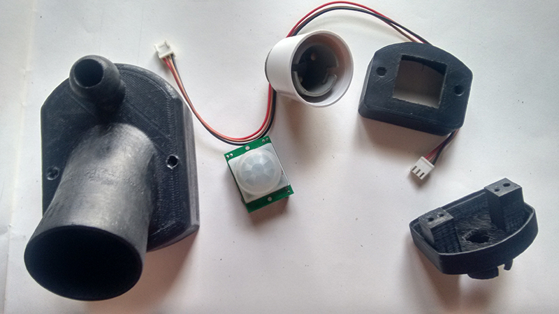
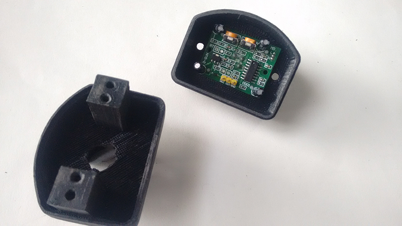
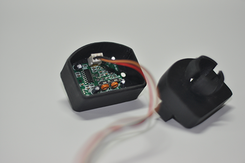
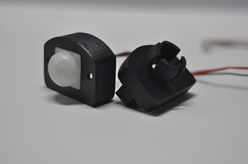
I had designed the casing for my motion sensing light before. It consists of two parts, one to hold the PCB and the other for the motion sensor.
3d printed casing for the motion sensing light
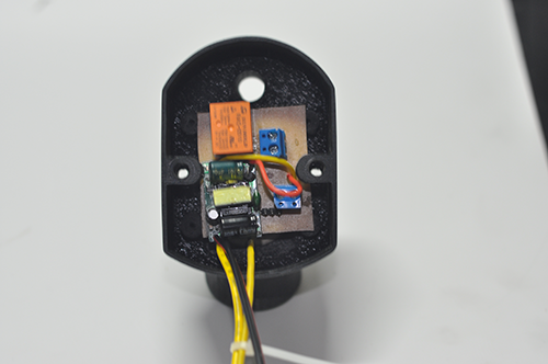
I wanted to run this motion sensor at 230 V AC power supply thus a Relay circuit was required to do the switching
I modified the board made by Neil and designed my own board using Attiny 45
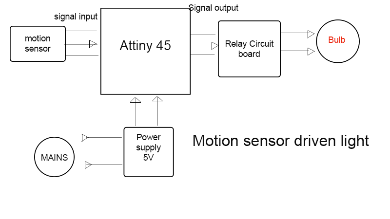
The block diagram for my board is shown in the diagram below.
block diagram for my board
Here I am using PIR sensor to detach the motion of a person, this motion sensor will send a signal to the IC which will trigger the relay and ultimately the light bulb.
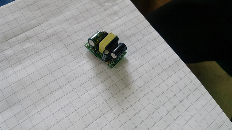
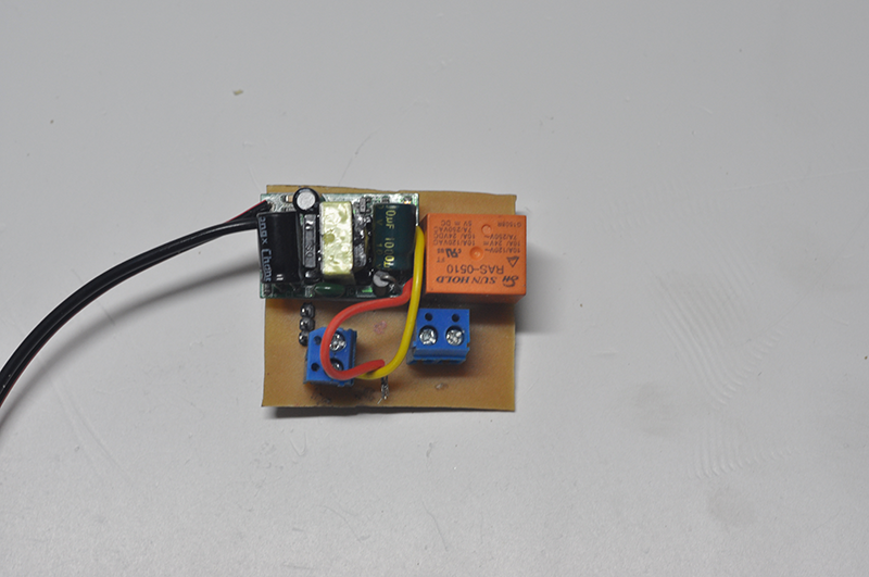
The motion sensor and the relay board both use 5V DC supply thus I am using a 230V AC to 5V DC power supply in this circuit, this one is usually found in the mobile charger that we use. This will be the first time I willl be experimenting with AC power supply
Power supply used for the circuit
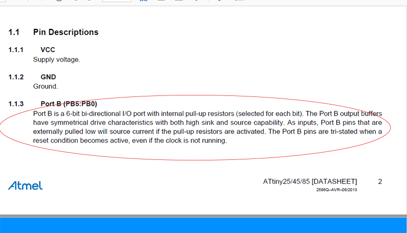
I went through the datasheet of the Attiny 45 IC to look for the pin diagram, it has 8 pins out of 6 pins except the ground and the VCC can be bi-directional input/output pins.
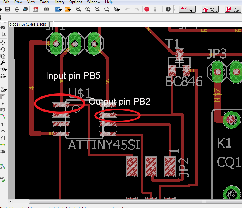
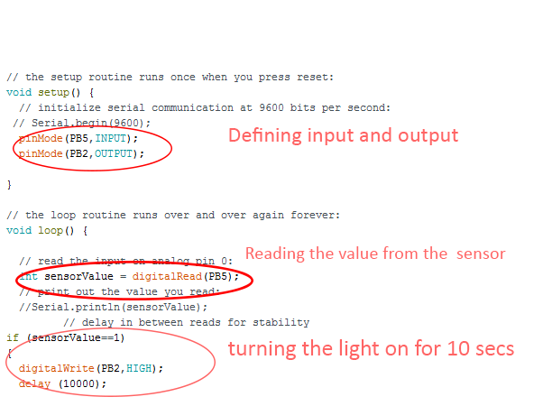
Thus I declared PB5 as my input pin which will get a input from the motion sensor and PB2 as my output pin to send a signal to the relay circuit board.
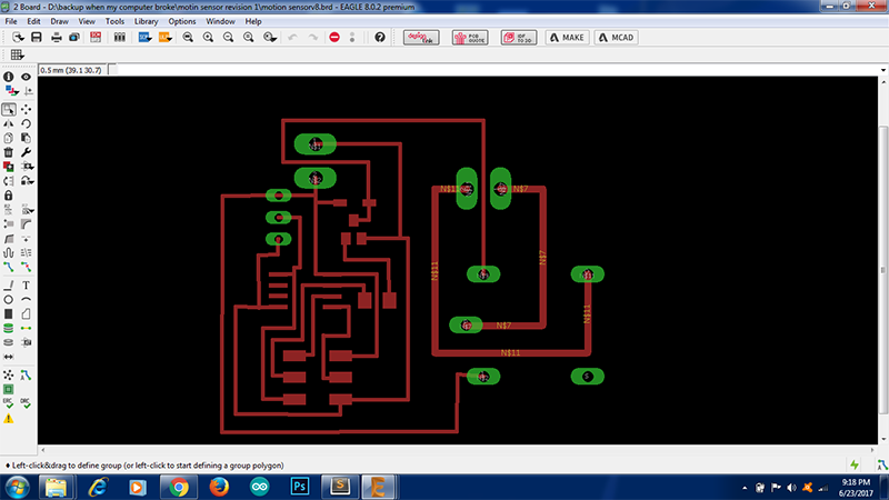
I am using Eagle to design my PCB.
Before starting I searched for Basic relay board on the internet this gives us the minimum number of components required for the circuit, In my case the signal goes to the relay through a resistor and a transistor which I included in the PCB.
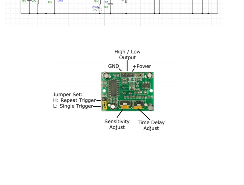
The next thing I did was to go throught the datasheet of the PIR sensor I was going to use, I found out the pin configuration and made provision for 1*3 Pin head on the circuit board
Pir sensor pin configuration
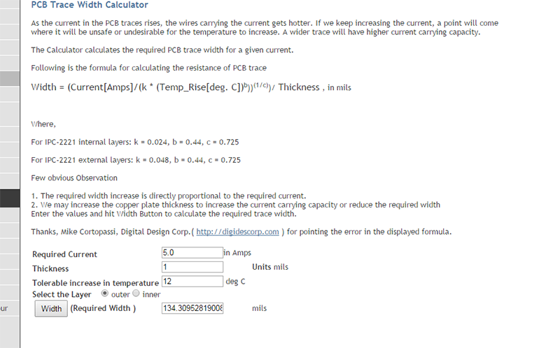
As my circuit is going to have a 230V ac supply and a current not more 5 Amp I had to change the width of the track for this section,I went through a website which gives us the widht of the track as per the current passing by it and increased the same in the design
I have several through hole connectors in my board which I plan to drill using a hand drill if not made properly by the modella machine.
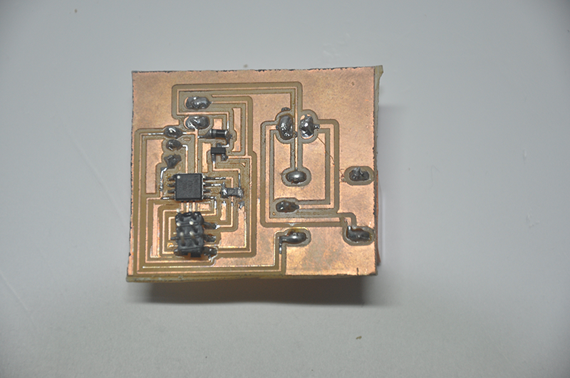
I milled the board and soldered it, I checked the connectivity to see if there is any short in the board. The board fits nicely in my 3d printed enclosure.
Download the code for the board from here, I used arduino as a programmer and arduino IDE to program the board.
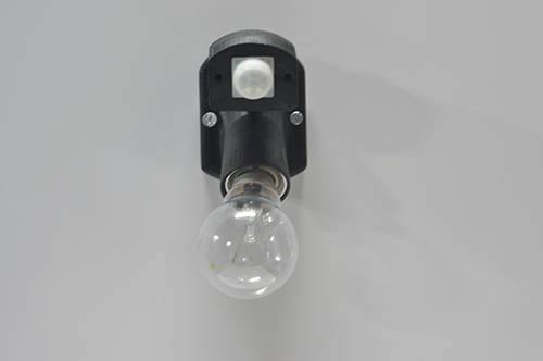
The motion sensor senses the whole room and is very sensitive, there is adjustment screws at the bottom of the motion sensor for the delay and the sensitivity.
I have programmed the board so that it switches on the bulb when it senses a motion for 10 seconds and it switched off after it stops sensing the motion with a delay of 10 secs, I need to figure out how to keep the bulb on untill the person is inside the room and switched off after it stops doing so. Maybe some other type of sensor is the solution.